Automatic Hi-Pot Testing Machine with PLC Control Integrated into a One Piece Flow Production System
Busbar insulation testing at PT. Flextronics Technology Indonesia was previously performed manually at up to 1890 VAC, exposing operators to a high risk of electrical hazard. This project automates the Hi-Pot testing process by integrating a Hi-Pot Test Unit (Metrel 3325) with a Mitsubishi FX3U PLC and relay module — sequencing the high-voltage test across six busbar points automatically, and integrating the station into a One Piece Flow assembly line.
Project Overview
PT. Flextronics Technology Indonesia is a PCB assembly manufacturer that continuously pursues process improvement through its Kaizen (Continuous Improvement) culture. One of its production lines assembles industrial busbars, where each process stage is separated by station and parts are moved manually between them using a trolley.
One critical stage in this line is insulation testing using Hi-Pot (High Potential) test, performed manually at up to 1890 VAC. This manual procedure exposed operators to a significant risk of electrical hazard, making it a priority target for improvement.
Applying the Kaizen concept, this project redesigns the busbar assembly line into a One Piece Flow production system, where assembly, testing, and packing stations are connected by a single conveyor line, and the Hi-Pot test itself is fully automated through PLC control — removing the operator from direct contact with high voltage.
Problem Statement
- How can the Hi-Pot insulation test on the busbar assembly line be performed automatically, without exposing operators to high-voltage hazards?
- How can the Hi-Pot Test Unit be connected to and sequenced by a PLC within a One Piece Flow line?
- Build an automatic Hi-Pot testing system, PLC-controlled, integrated into the One Piece Flow busbar assembly line.
Objectives
System Design & Development
The system integrates three main components: a Hi-Pot Test Unit (Metrel 3325) that generates the high-voltage insulation test, a Mitsubishi FX3U-48 PLC that sequences the entire test cycle, and a 10-channel relay module (HRM24-6A06) that routes the high voltage to six busbar test points across 15 test combinations.
Site Visit & Kaizen Brainstorming
Site visit to the Flex AM line to study the busbar assembly process and identify the manual Hi-Pot test as a safety and efficiency improvement target.
System Architecture Design
Designing the signal & high-voltage flow between the Hi-Pot Test Unit, PLC, and relay module, along with the relay sequence table for the 15 test combinations.
PLC & Relay Wiring
Wiring the PLC I/O, 10 relay coils, and probe cylinders, then integrating the testing station into the One Piece Flow conveyor layout.
Automatic Sequence Testing
Running the automatic sequence and validating the Pass/Fail signal against known-good and known-fault busbar samples.

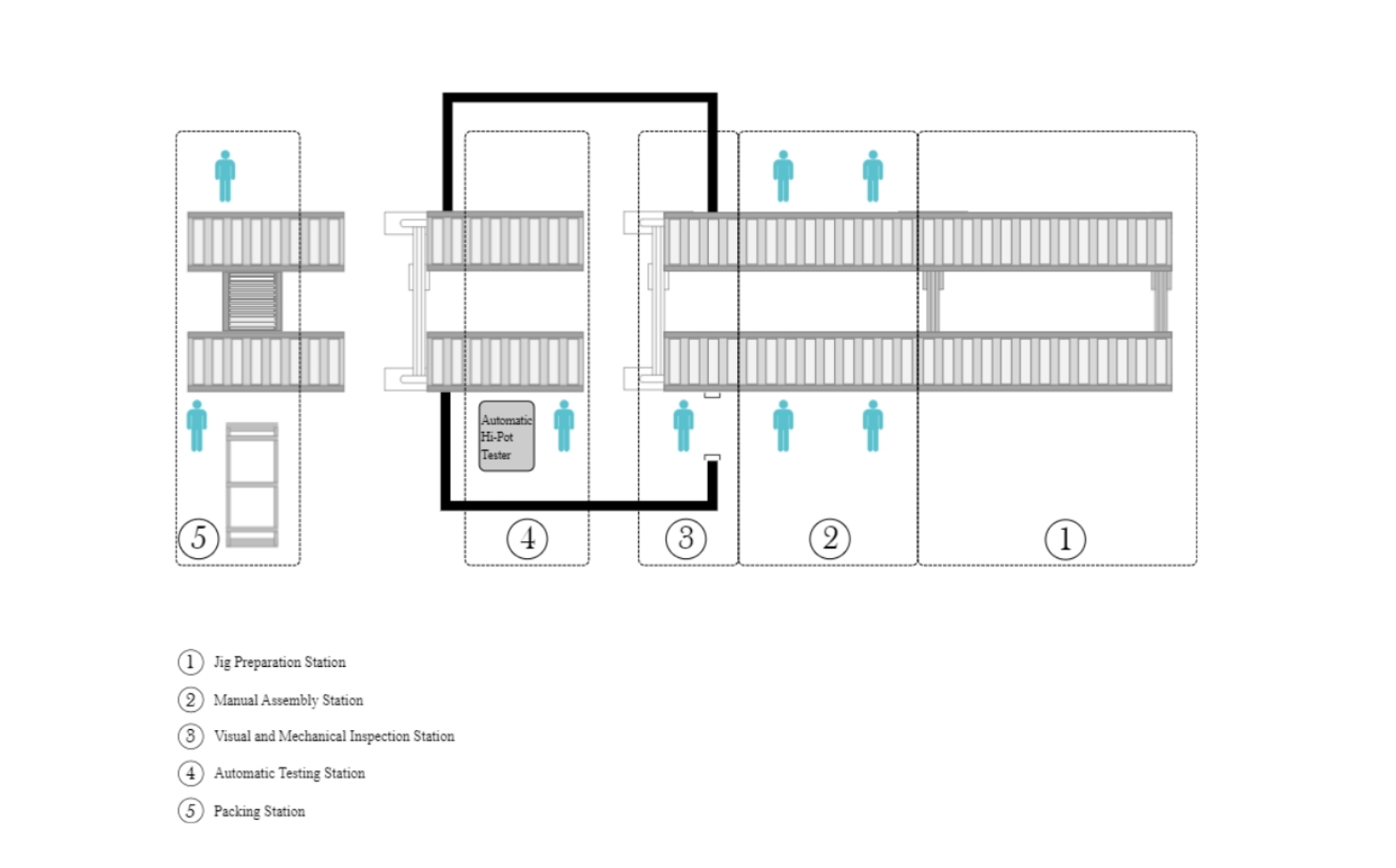
| System Specifications | Value |
|---|---|
| Test Voltage (HV AC) | up to 1890 VAC |
| Reject Threshold | > 10 mA |
| Busbar Test Points | 6 points |
| Test Combinations | 15 sequences |
| Sequence Timing (Per sequences) | 4 s |
Hardware Components
- Metrel 3325 – High-voltage insulation tester for automated Hi-Pot testing
- Mitsubishi FX3U-48 PLC – Central controller coordinating the test sequence
- Relay Module HRM24-6A06 – Switch high voltage to the required busbar test points
- Pneumatic Cylinder – Positions the test probes automatically
- Tower Lamp – Visual indicator for HV active (yellow), Pass (green), Fail (red)
Implementation & Results
The system was evaluated first on its impact on operator safety, and then on the accuracy and timing of the automatic Hi-Pot sequence itself, comparing the manual (before) and the automated (after) testing process.
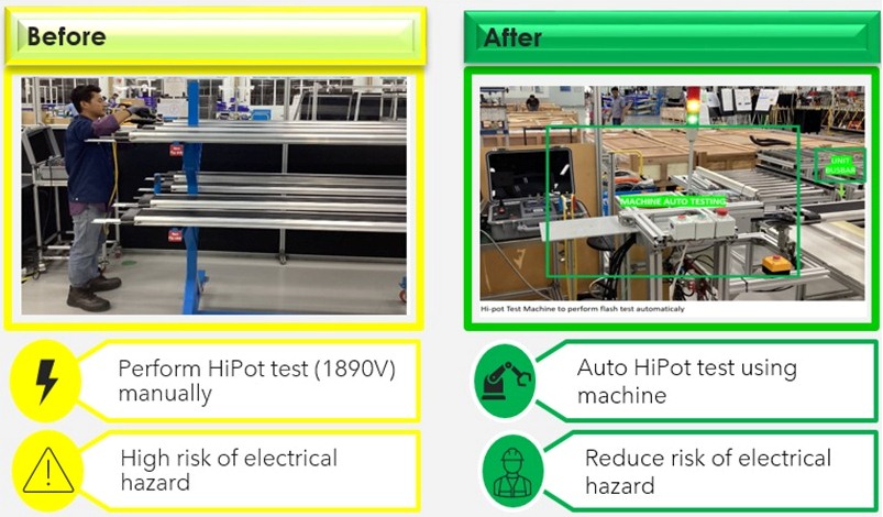
Safety Improvement: Before vs. After
Previously, operators performed the 1890 VAC Hi-Pot test manually with hand-held probes, placing them at direct risk of electrical hazard. After implementation, the probes are positioned automatically by pneumatic cylinders and the test is triggered and read entirely by the PLC — removing the operator from direct contact with high voltage while the machine performs the test automatically.
Automatic Sequence Test Results
The automatic Hi-Pot system was tested on twenty busbar samples — ten expected to Pass and ten deliberately fitted with a fault expected to Fail. Every sample was read correctly by the system: a single Fail reading in any of the 15 sequence steps immediately shuts off the HV and returns the mechanism to its home position, while a full Pass reading across all 15 steps is reported as an overall Pass.
| Test Set | Samples | Correct Reading | Result |
|---|---|---|---|
| Good busbar (expected Pass) | 10 | 10 / 10 | All Pass |
| Faulty busbar (expected Fail) | 10 | 10 / 10 | All Fail, HV auto cut-off |
| Overall accuracy | 20 | 20 / 20 | 100% |
Cycle & Sequence Timing
Each of the 15 test conditions is held for 4 s, so a complete 15-step sequence takes 60 s (1 minute). Including probe positioning and retraction, one full testing cycle takes approximately 152 s. Pass results turn on the green indicator lamp, while a Fail immediately cuts the HV signal, lights the red lamp, and holds it until the emergency button is pressed.
System Validation Data
Full sequence-by-sequence data for all 20 trials — each row shows the reading of every one of the 15 test combinations. A dash (–) marks a step that was not reached because the sequence was already halted by an earlier Fail.
| No | Checking Sequence | Results | ||||||||||||||
|---|---|---|---|---|---|---|---|---|---|---|---|---|---|---|---|---|
| 1 | 2 | 3 | 4 | 5 | 6 | 7 | 8 | 9 | 10 | 11 | 12 | 13 | 14 | 15 | ||
| 1 | Pass | Pass | Pass | Pass | Pass | Pass | Pass | Pass | Pass | Pass | Pass | Pass | Pass | Pass | Pass | Pass |
| 2 | Pass | Pass | Pass | Pass | Pass | Pass | Pass | Pass | Pass | Pass | Pass | Pass | Pass | Pass | Pass | Pass |
| 3 | Pass | Pass | Pass | Pass | Pass | Pass | Pass | Pass | Pass | Pass | Pass | Pass | Pass | Pass | Pass | Pass |
| 4 | Pass | Pass | Pass | Pass | Pass | Pass | Pass | Pass | Pass | Pass | Pass | Pass | Pass | Pass | Pass | Pass |
| 5 | Pass | Pass | Pass | Pass | Pass | Pass | Pass | Pass | Pass | Pass | Pass | Pass | Pass | Pass | Pass | Pass |
| 6 | Pass | Pass | Pass | Pass | Pass | Pass | Pass | Pass | Pass | Pass | Pass | Pass | Pass | Pass | Pass | Pass |
| 7 | Pass | Pass | Pass | Pass | Pass | Pass | Pass | Pass | Pass | Pass | Pass | Pass | Pass | Pass | Pass | Pass |
| 8 | Pass | Pass | Pass | Pass | Pass | Pass | Pass | Pass | Pass | Pass | Pass | Pass | Pass | Pass | Pass | Pass |
| 9 | Pass | Pass | Pass | Pass | Pass | Pass | Pass | Pass | Pass | Pass | Pass | Pass | Pass | Pass | Pass | Pass |
| 10 | Pass | Pass | Pass | Pass | Pass | Pass | Pass | Pass | Pass | Pass | Pass | Pass | Pass | Pass | Pass | Pass |
| 1 | Pass | Pass | Pass | Fail | - | - | - | - | - | - | - | - | - | - | - | Fail |
| 2 | Pass | Pass | Fail | - | - | - | - | - | - | - | - | - | - | - | - | Fail |
| 3 | Pass | Pass | Fail | - | - | - | - | - | - | - | - | - | - | - | - | Fail |
| 4 | Pass | Pass | Pass | Pass | Fail | - | - | - | - | - | - | - | - | - | - | Fail |
| 5 | Pass | Pass | Pass | Pass | Pass | Pass | Fail | - | - | - | - | - | - | - | - | Fail |
| 6 | Pass | Pass | Pass | Pass | Fail | - | - | - | - | - | - | - | - | - | - | Fail |
| 7 | Pass | Pass | Pass | Pass | Pass | Pass | Fail | - | - | - | - | - | - | - | - | Fail |
| 8 | Pass | Pass | Pass | Pass | Pass | Pass | Fail | - | - | - | - | - | - | - | - | Fail |
| 9 | Pass | Fail | - | - | - | - | - | - | - | - | - | - | - | - | - | Fail |
| 10 | Pass | Pass | Pass | Pass | Pass | Pass | Pass | Fail | - | - | - | - | - | - | - | Fail |
Performance Summary
The Automatic Hi-Pot Testing Machine successfully runs the full insulation test cycle under PLC control, completing each 15-step sequence in 60 seconds and a full test cycle in approximately 152 seconds, with the Hi-Pot Test Unit reporting Pass/Fail results in real time through the tower lamp indicators.
Across 20 validation trials, the system achieved 100% reading accuracy, and by automating probe placement and HV control, the project removed the operator from direct exposure to the 1890 VAC test — directly addressing the electrical safety issue that motivated the project, while integrating the station into a One Piece Flow busbar assembly line.